Vector group is the International Electrotechnical Commission (IEC) method of categorizing the high-voltage (HV) windings and low-voltage (LV) winding configurations of three-phase transformers. It provides critical information about the winding connections and the phase angle difference between them.
The table below outlines common vector group designations:
| Vector Group | HV Connection | LV Connection | Phase Angle Difference |
|---|---|---|---|
| Dyn11 | Delta | Wye | +30° |
| Yd11 | Wye | Delta | +30° |
| Dyn1 | Delta | Wye | -30° |
| Yy0 | Wye | Wye | 0° |
Selecting the appropriate vector group is essential for ensuring the compatibility and performance of transformers within a specific application. The process involves evaluating:
System Configuration Requirements: Ensure that the transformer’s vector group matches the network’s requirements for voltage, phase angle, and grounding.
Parallel Operation: If the transformer will operate in parallel with others, they must share the same vector group. Discrepancies can cause circulating currents and system imbalances.
Load Characteristics: Certain loads, such as large motors or rectifiers, may impose specific requirements on the transformer’s connection and phase shift.
Utility Standards: Utilities may mandate specific vector groups for transformers connected to their grids.
Transformer Application: For example, Dyn11 is common in distribution networks, while Yy0 is often used for interconnecting transmission systems.
The vector group plays a vital role in the operation and performance of transformers. Here are some key reasons:
Parallel Operation Compatibility
System Stability
Fault Management: Understanding the vector group helps in diagnosing faults and designing protective schemes.
Energy Efficiency: Aligning vector groups with load requirements can optimize energy transfer and minimize losses.
Testing the vector group of a transformer is a standard procedure during manufacturing and commissioning. Here are the key steps:
Prepare the Transformer:
Apply Voltage
Measure Phase Voltages: Record the induced voltages on the LV side and note their magnitudes and polarities.
Determine Phase Shift: Analyze the relationship between the HV and LV voltages using a vector diagram.
Verify Results: Compare the measured data with the manufacturer’s specifications or expected vector group designation.
Changing the vector group of a transformer is not straightforward and involves significant modifications. Common challenges include:
Winding Reconnection: Reconfiguring windings to alter the vector group can be complex and may require extensive rewiring.
Magnetic Core Considerations: The core design is optimized for a specific vector group, so changes can affect efficiency and performance.
System Compatibility: A new vector group might not align with the existing network’s requirements, necessitating further system adjustments.
Cost and Downtime: Modifications can be costly and result in extended operational downtime.
Vector groups are critical in various transformer applications. Some practical examples include:
Distribution Networks: Dyn11 transformers are commonly used to step down voltage for distribution to end users while ensuring compatibility with grounded systems.
Industrial Loads: Delta-wye configurations (e.g., Yd11) provide phase shift benefits and isolate the HV side from harmonic currents generated by industrial loads.
Renewable Energy Systems: Transformers in wind and solar power applications often require specific vector groups to integrate seamlessly with inverters and grid connections.
Interconnecting Grids
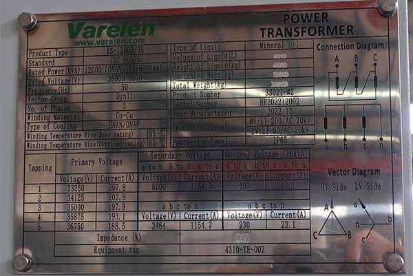
The IEC method introduces vector groups for categorizing the three-phase transformer winding configurations. Windings may be connected in delta, star, or zigzag. The polarity of the windings is also important because it affects their phase relationship. All of this information can be easily provided through vector groups. Always make sure to study them on transformer nameplates before connecting the transformer to the power system.